
ASUS UX360C BIOS password read
We recovered the BIOS administrator password from an ASUS UX360C by analyzing an 8 MiB SPI flash dump read with an RT809H programmer. The recovered administrator password was then accepted by the laptop, restoring access to BIOS Setup.
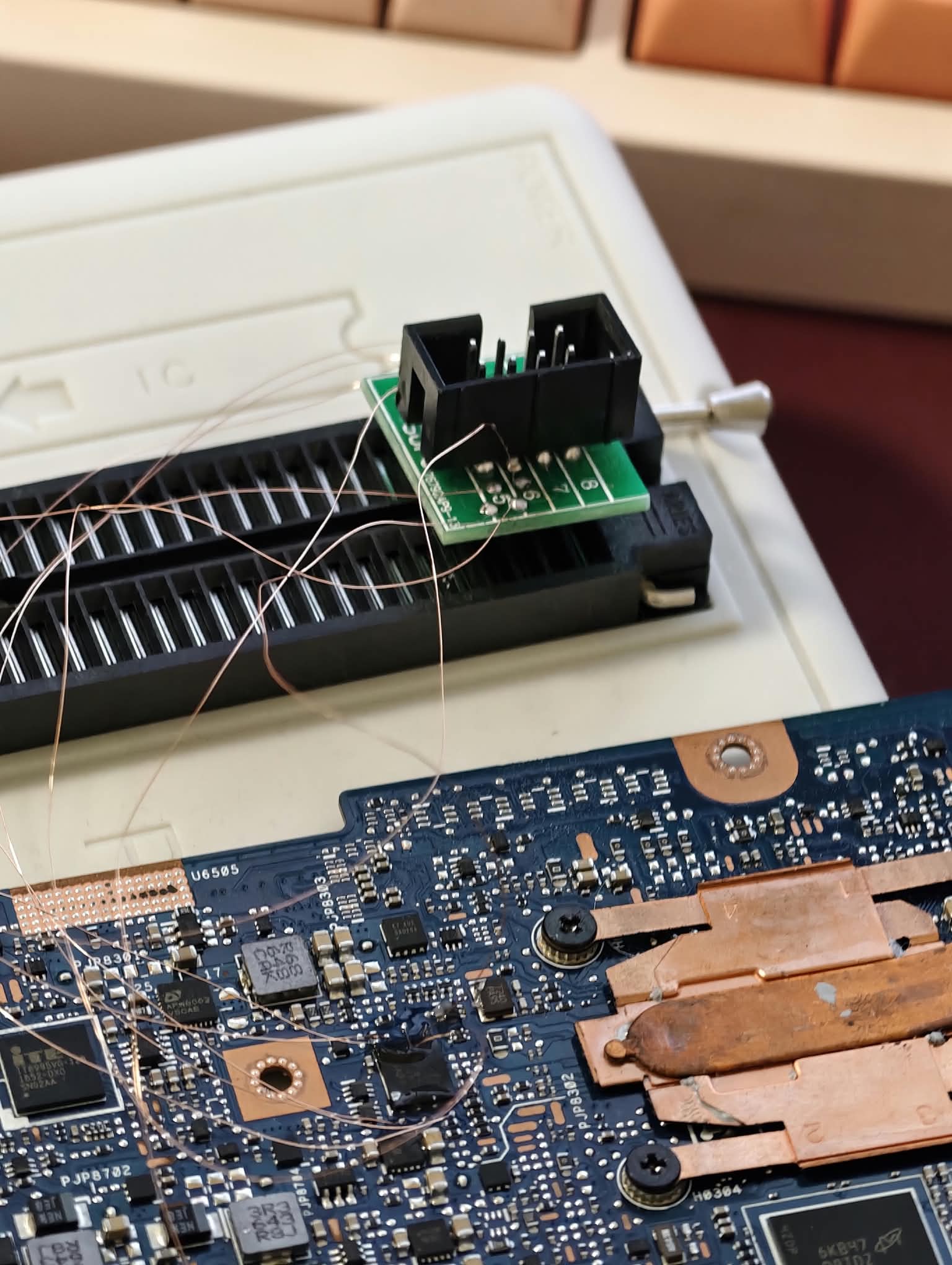
The SPI flash stayed on the motherboard during reading. Fine wires connected the board to a small adapter seated in the RT809H ZIF socket. The original bench photographs below show this setup.
All passwords shown in this article and its promotional artwork are fictional replacements. DemoOnly42! is an example, not the recovered password or a universal ASUS password.
CASE AT A GLANCEDevice: ASUS UX360CProgrammer: RT809HRead method: In-circuit SPI read through soldered fine wiresFlash family: Winbond W25Q64 seriesDump size: 8,388,608 bytes — 8 MiB / 64 MbitRecord analyzed: AMITSESetup in the NVRAM areaResult: Recovered administrator password accepted at BIOS SetupFirmware changes: None made during the recovery analysis; no modified BIOS was flashed
1. READ THE ORIGINAL SPI FLASH
We used the RT809H to obtain a full binary readout from the laptop's BIOS flash. The chip remained soldered to the motherboard, with fine wires routed to the programmer adapter rather than removing the chip for this read.
For this type of connection, identify the actual chip, its supply voltage, pin 1 and the adapter's mapping before applying power. The laptop's normal power sources must be disconnected while the programmer is attached. Keep the signal wires short and avoid loose conductors touching adjacent components.
The usual eight-pin W25Q64FV signal layout is:
Chip pin | Signal1 | /CS2 | DO / IO1 / MISO3 | /WP / IO24 | GND5 | DI / IO0 / MOSI6 | CLK7 | /HOLD / IO38 | VCC
This is a chip signal reference, not a numbered RT809H ZIF socket map. Follow the selected chip algorithm and the actual adapter arrangement. The photographs document our setup but do not clearly resolve every wire endpoint, so they should not be used as a substitute for continuity checks.
Our saved readout was 8,388,608 bytes, matching a 64 Mbit flash image. For a new recovery, take at least two independent reads and compare them before trusting the data. A correct file size alone does not prove a clean read. In-circuit reads can be affected by other devices connected to the same bus.
2. PRESERVE THE ORIGINAL DUMP
The original file was kept intact and inspected offline. The analysis used read-only access; no erase, program, password-reset patch or replacement BIOS image was required.
Use a working copy for investigation and keep the original privately. A complete BIOS dump may contain device identifiers and security-related data, so it is not included in this public case-study package.
3. LOCATE THE AMITSESetup RECORD
In the complete binary, we located the AMITSESetup name and checked the surrounding NVAR record header and its size. This established the data boundary before interpreting the password fields.
A text match by itself is not enough. NVRAM may contain multiple or obsolete records, and other firmware versions may use a different layout. A structured UEFI/NVRAM viewer can help inspect the record, but our case was analyzed directly from the supplied full dump.
4. IDENTIFY THE TWO PASSWORD FIELDS
The record layout used in this case had two 40-byte fields at the start of the AMITSESetup data:
Relative data offset | Length | Meaning0x00–0x27 | 40 bytes | User password field0x28–0x4F | 40 bytes | Administrator password field
These are offsets inside the variable's data, not fixed addresses in every ASUS BIOS. The administrator field was the relevant one for entering BIOS Setup with administrator access.
5. DECODE WITH THE CORRECT ALIGNMENT
For this record, each 40-byte field was XOR-decoded using the published AMI constant documented by the AsusMadeMeCry project. The decoded bytes were interpreted as UTF-16 little-endian text, stopping at the first null character.
Conceptually:
stored 40-byte field → XOR with the matching 40-byte constant → UTF-16 LE text
The key alignment restarts at the beginning of each field. An earlier cropped hex fragment started partway through a field, which produced an incomplete interpretation. Returning to the complete record and its verified boundary resolved that ambiguity.
This was decoding a reversible representation in the examined firmware, not brute-forcing a password. A readable candidate still needs device-side verification; a string found in a dump is not automatically the active password.
The accompanying Demo_AMITSESetup_Decode.py illustrates the field-decoding step using entirely synthetic values. It does not open a real BIOS dump, parse NVRAM or write to hardware.
6. VERIFY ON THE LAPTOP
After decoding the two fields, we distinguished the user password from the administrator password by their positions in the record. The administrator password was then entered on the ASUS UX360C, and BIOS Setup access was restored.
Public example output — fictional values only:
User password: DemoUser42Administrator password: DemoOnly42!
The real values are withheld. The artwork's example password and BIOS-style panel are illustrative and are not a photograph of the actual successful login.
ORIGINAL BENCH PHOTOGRAPHS
Photo 1 — RT809H adapter connectionFine wires connect the motherboard to the small adapter seated in the RT809H ZIF socket.File: 01_Original_RT809H_Adapter_Connection.jpeg
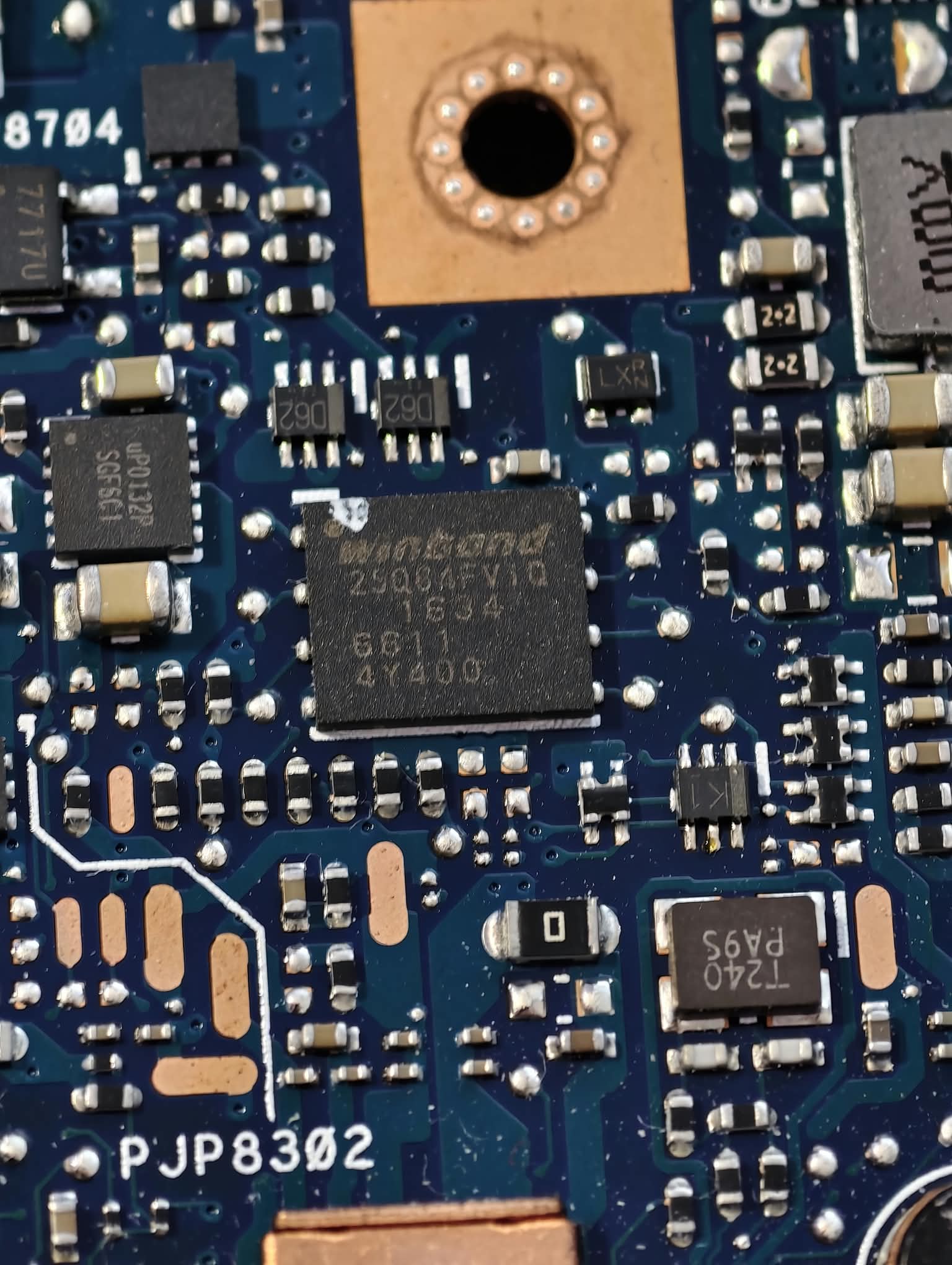
Photo 2 — SPI flash close-upClose-up of the Winbond W25Q64-family flash on the ASUS motherboard.File: 02_Original_Winbond_SPI_Flash_Closeup.jpeg
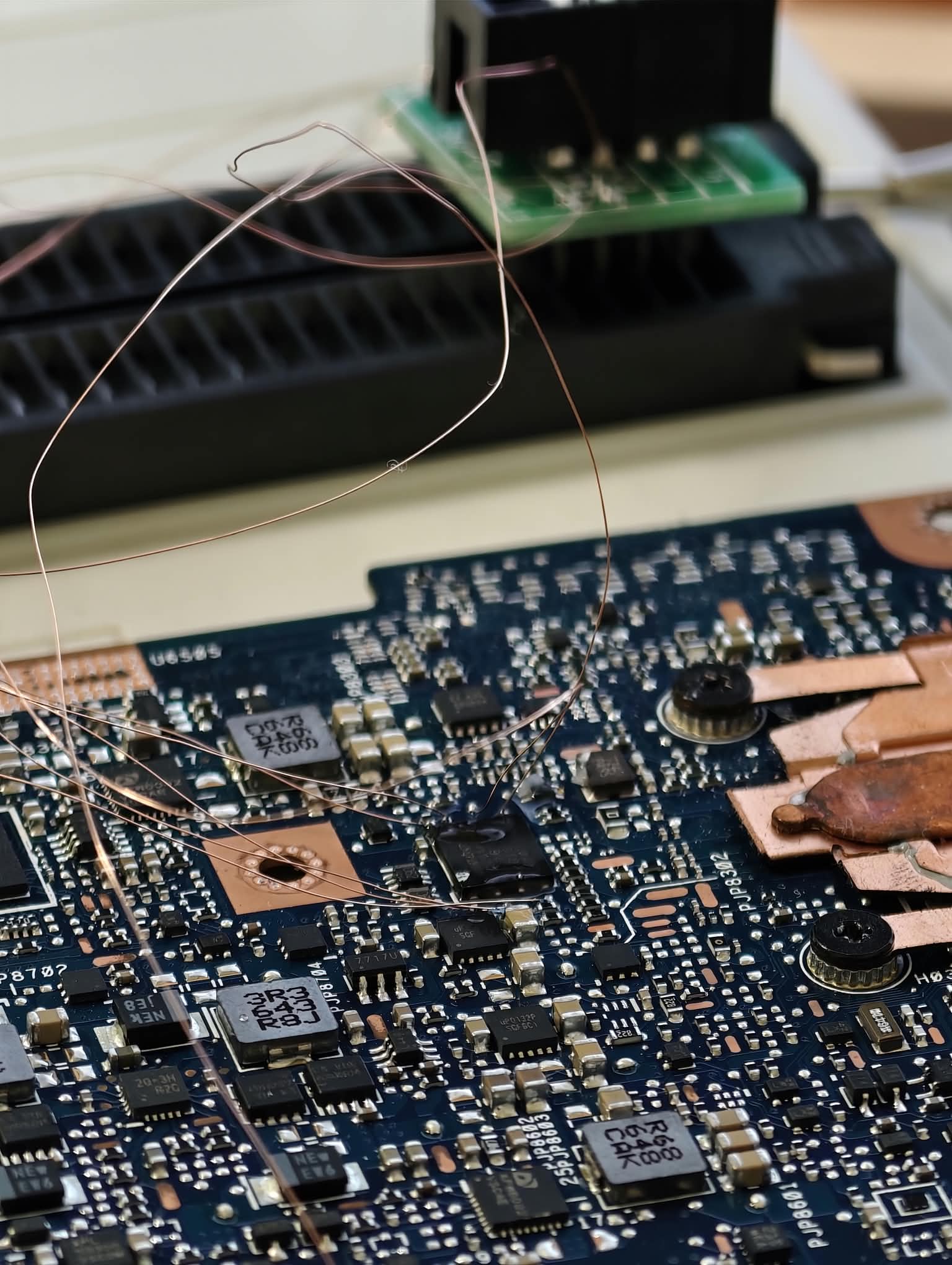
Photo 3 — In-circuit wiring overviewOverview of the soldered fine-wire connection, with the flash remaining on the motherboard.File: 03_Original_InCircuit_Wiring_Overview.jpeg
The three bench photos are supplied by the technician who performed the work and are provided unchanged. The website and Instagram cover images are separately labeled illustrations.
WHAT THIS RESULT ESTABLISHES
On this ASUS UX360C and the examined firmware, the RT809H readout contained an AMITSESetup record whose administrator password could be decoded and verified on the device. No modified BIOS needed to be written for this recovery.
This is a documented result for this unit and firmware. Other ASUS models or BIOS versions may use different storage layouts or password protection.
REFERENCES AND CREDIT
AMI field layout and public decoding reference:https://github.com/anubhavg-icpl/AsusMadeMeCry#technical-details
Reference implementation:https://github.com/anubhavg-icpl/AsusMadeMeCry/blob/master/AMITSEDecrypt.py
Winbond W25Q64FV datasheet:https://media.digikey.com/pdf/Data%20Sheets/Winbond%20PDFs/W25Q64FV_Rev_S.pdf
The public research is credited to its authors. This article documents GSMLeaks' own readout, analysis and technician-confirmed result.
The SPI flash stayed on the motherboard during reading. Fine wires connected the board to a small adapter seated in the RT809H ZIF socket. The original bench photographs below show this setup.
All passwords shown in this article and its promotional artwork are fictional replacements. DemoOnly42! is an example, not the recovered password or a universal ASUS password.
CASE AT A GLANCEDevice: ASUS UX360CProgrammer: RT809HRead method: In-circuit SPI read through soldered fine wiresFlash family: Winbond W25Q64 seriesDump size: 8,388,608 bytes — 8 MiB / 64 MbitRecord analyzed: AMITSESetup in the NVRAM areaResult: Recovered administrator password accepted at BIOS SetupFirmware changes: None made during the recovery analysis; no modified BIOS was flashed
1. READ THE ORIGINAL SPI FLASH
We used the RT809H to obtain a full binary readout from the laptop's BIOS flash. The chip remained soldered to the motherboard, with fine wires routed to the programmer adapter rather than removing the chip for this read.
For this type of connection, identify the actual chip, its supply voltage, pin 1 and the adapter's mapping before applying power. The laptop's normal power sources must be disconnected while the programmer is attached. Keep the signal wires short and avoid loose conductors touching adjacent components.
The usual eight-pin W25Q64FV signal layout is:
Chip pin | Signal1 | /CS2 | DO / IO1 / MISO3 | /WP / IO24 | GND5 | DI / IO0 / MOSI6 | CLK7 | /HOLD / IO38 | VCC
This is a chip signal reference, not a numbered RT809H ZIF socket map. Follow the selected chip algorithm and the actual adapter arrangement. The photographs document our setup but do not clearly resolve every wire endpoint, so they should not be used as a substitute for continuity checks.
Our saved readout was 8,388,608 bytes, matching a 64 Mbit flash image. For a new recovery, take at least two independent reads and compare them before trusting the data. A correct file size alone does not prove a clean read. In-circuit reads can be affected by other devices connected to the same bus.
2. PRESERVE THE ORIGINAL DUMP
The original file was kept intact and inspected offline. The analysis used read-only access; no erase, program, password-reset patch or replacement BIOS image was required.
Use a working copy for investigation and keep the original privately. A complete BIOS dump may contain device identifiers and security-related data, so it is not included in this public case-study package.
3. LOCATE THE AMITSESetup RECORD
In the complete binary, we located the AMITSESetup name and checked the surrounding NVAR record header and its size. This established the data boundary before interpreting the password fields.
A text match by itself is not enough. NVRAM may contain multiple or obsolete records, and other firmware versions may use a different layout. A structured UEFI/NVRAM viewer can help inspect the record, but our case was analyzed directly from the supplied full dump.
4. IDENTIFY THE TWO PASSWORD FIELDS
The record layout used in this case had two 40-byte fields at the start of the AMITSESetup data:
Relative data offset | Length | Meaning0x00–0x27 | 40 bytes | User password field0x28–0x4F | 40 bytes | Administrator password field
These are offsets inside the variable's data, not fixed addresses in every ASUS BIOS. The administrator field was the relevant one for entering BIOS Setup with administrator access.
5. DECODE WITH THE CORRECT ALIGNMENT
For this record, each 40-byte field was XOR-decoded using the published AMI constant documented by the AsusMadeMeCry project. The decoded bytes were interpreted as UTF-16 little-endian text, stopping at the first null character.
Conceptually:
stored 40-byte field → XOR with the matching 40-byte constant → UTF-16 LE text
The key alignment restarts at the beginning of each field. An earlier cropped hex fragment started partway through a field, which produced an incomplete interpretation. Returning to the complete record and its verified boundary resolved that ambiguity.
This was decoding a reversible representation in the examined firmware, not brute-forcing a password. A readable candidate still needs device-side verification; a string found in a dump is not automatically the active password.
The accompanying Demo_AMITSESetup_Decode.py illustrates the field-decoding step using entirely synthetic values. It does not open a real BIOS dump, parse NVRAM or write to hardware.
6. VERIFY ON THE LAPTOP
After decoding the two fields, we distinguished the user password from the administrator password by their positions in the record. The administrator password was then entered on the ASUS UX360C, and BIOS Setup access was restored.
Public example output — fictional values only:
User password: DemoUser42Administrator password: DemoOnly42!
The real values are withheld. The artwork's example password and BIOS-style panel are illustrative and are not a photograph of the actual successful login.
ORIGINAL BENCH PHOTOGRAPHS
Photo 1 — RT809H adapter connectionFine wires connect the motherboard to the small adapter seated in the RT809H ZIF socket.File: 01_Original_RT809H_Adapter_Connection.jpeg
Photo 2 — SPI flash close-upClose-up of the Winbond W25Q64-family flash on the ASUS motherboard.File: 02_Original_Winbond_SPI_Flash_Closeup.jpeg
Photo 3 — In-circuit wiring overviewOverview of the soldered fine-wire connection, with the flash remaining on the motherboard.File: 03_Original_InCircuit_Wiring_Overview.jpeg
The three bench photos are supplied by the technician who performed the work and are provided unchanged. The website and Instagram cover images are separately labeled illustrations.
WHAT THIS RESULT ESTABLISHES
On this ASUS UX360C and the examined firmware, the RT809H readout contained an AMITSESetup record whose administrator password could be decoded and verified on the device. No modified BIOS needed to be written for this recovery.
This is a documented result for this unit and firmware. Other ASUS models or BIOS versions may use different storage layouts or password protection.
REFERENCES AND CREDIT
AMI field layout and public decoding reference:https://github.com/anubhavg-icpl/AsusMadeMeCry#technical-details
Reference implementation:https://github.com/anubhavg-icpl/AsusMadeMeCry/blob/master/AMITSEDecrypt.py
Winbond W25Q64FV datasheet:https://media.digikey.com/pdf/Data%20Sheets/Winbond%20PDFs/W25Q64FV_Rev_S.pdf
The public research is credited to its authors. This article documents GSMLeaks' own readout, analysis and technician-confirmed result.